ME-61/GRC
ME-61/GRC PREAMPLIER
ME-61/GRC
INTRODUCTION
When experimenting with antennas or antenna couplers it is almost a must to have a field strength meter to determine which antenna is the best or which antenna tuner has the least losse
. Such a measuring system is easy DIY and on the internet you can find a variety of designs.
Although in possession of such a home brew meter, I still looked forward for an vintage military ME-161 GRC. Not because it was necessary, but only to 'have' it! It belongs to an AN/GRC9 system and many hams in the Netherlands own this ex military set.

 During my military training and exercises I frequently worked with an AN/GRC9 mounted in a one-ton DAF YA-126 also called Web. For any reason an ME-61/GRC was never included.
For a better match of the antenna, I used the dashboard bulb of the YA-126 as an antenna current meter.
First the ¼ wave antenna for the operating frequency was calculated and then made to length from a field telephone line (WD1TT).
The bulb was temporarily installed between antenna terminal and wire. Then the antenna was 'tuned' to the maximum illumination. Thanks to this method and because CW was the standard mode, a workable telegraph communication was almost guaranteed.
BTW did you notice that an YA-126 takes part in many action films?
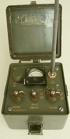
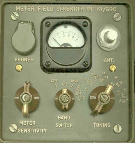
ME-61/GRC
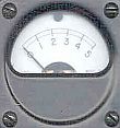 The instrument is waterproof if the solid aluminum box is closed and the gaskets still do their work. The lettering is engraved and filled with probably white paint, but that has been yellowed over time.
The measuring system is not too sensitive, because a few meters from the antenna with 100 W on 80 m, the needle only covers one division.
On the internet are designs to increase the sensitivity with an amplifier after the diode rectifier. That requires quite a few changes in the original circuit, but it can be simpler with an HF preamplifier between tuned circuit and detector.
PREAMPLIFIER
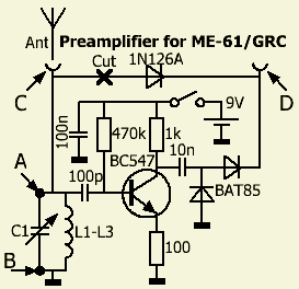
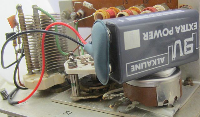
The preamplifier is nothing special and is made with components from the junk box. The power consumption from a 9 V battery is approximately 5 mA. To reduce the gain and prevent self-oscillation, an 100 Ohm negative feedback has been installed in the emitter.
The theoretical gain is 10, but the question is whether this is achieved by the dynamic load of the detector and voltage doubling with two BAT85 diodes. Nevertheless, the obtained gain is fine. Instead of one BAT85, the original 1N126A could also be used, but if one is installing the modification one can just as well mount two identical diodes.
INSTALLING
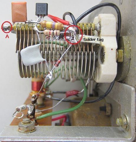
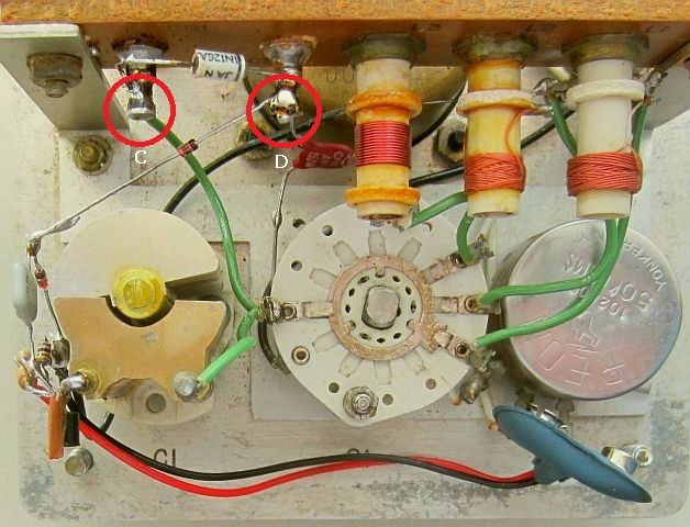
The installation is self-supporting, ie the two connections (points 'A' and 'B') of the variable capacitor C1 were used as mounting points. It may look messy, but all connections are short with only one earth/ground point. This promotes the HF properties. The original diode 1N126A is desoldered from point 'C' and from the new diode circuit a wire is connected to point 'D'.
When making changes to equipment, I try to make as little 'mess' as possible, so that it can be quickly recovered to the original circuit without any damage. A possible a new owner may not be charmed about the modifications.
Here, with the removal of the assembled components and resoldering of diode 1N126A, in no time the original circuit can be restored.
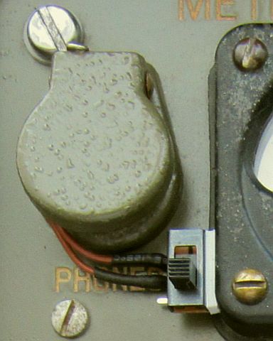
ON/OFF SWITCH
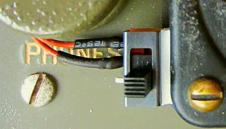
The above arguments argue that for a on/off switch no holes should be drilled in the front. Because the PHONES connection is not actually used here, wires can be fed through. A small type of slide switch provides the on and off function. It is glued to the side of the meter housing with two-side 'mirror' adhesive tape from TESA.
I can recommend this very strong two-side adhesive tape from TESA. After disappointing experience with other brands, I have found that it is the best of its kind. It is also used by me a lot and some heavy metal boxes with electronics have been stuck for about 10 years to the bottom of my desk.
The 9 V battery is also secured to the potentiometer with this adhesive tape.
![]()
![]()